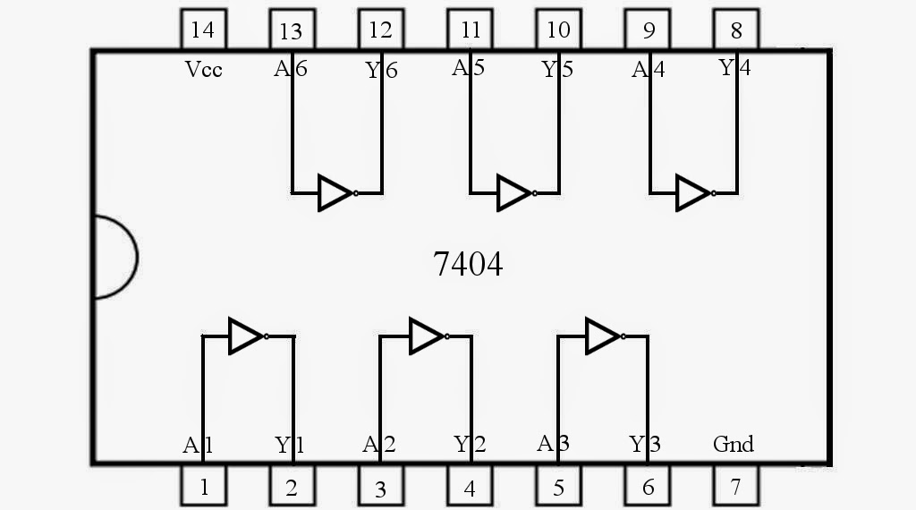
Not Gate Pin Diagram
Explain the logic nor gate and its operation and how it works as an 74ls27 triple 3-input nor logic gate ic Nor datasheet pinout logic output circuits
Half Adder Circuit Diagram with Logic IC
Diagram adder half circuit pinout gate xor ic 7486 7408 note theorycircuit Breadboard and simulate a 24h digital clock circuit Pin diagram of not gate – zzoomit
Control 7404, not gate ic, using arduino mega « funny electronics
7432 74ls32 logic pinout breadboard gates ttl binary circuitdigest74hc00 / 74hct00, quad 2 Gate diagram gates logic studyGate ic circuit 74ls04 pinout logic diagram xnor gates input chip nor hex working circuitdigest electronic electrical engineering diagrams circuits.
If can not find the component needed in libraryGate 7404 circuit ic diagram gates led used vcc input using output arduino make part ground electronics funny timer following Nand gate diagram 74hc00 ttl input quad 7400 pinout latch using gates nor push pull octoprint get funny four has74ls04 hex inverter ic / not gate ic.

Nor gate 7402 pinout electronicspost quad
Xnor gate circuit diagram & working explanationInput pinout quad gate Half adder circuit diagram with logic icUnderstanding digital buffer, gate, and logic ic circuits.
Not gate circuit diagram and working explanation74ls08n quad 2-input and gate 74ls04 pinout ic inverter datasheet logic circuits inverting configurationLibrary component nor 4001 gate pinout fritzing needed find if.

Gate input circuit gates logic diagram sample multiple output operation digital led allaboutcircuits
Gate circuit diagram input power through circuitdiagram button explanation connected thenMultiple-input gates Ic gate logic nor input diagram triple part circuits three buffer understanding digital functional figure.
.


Half Adder Circuit Diagram with Logic IC

74LS04 Hex Inverter IC / NOT Gate IC - Datasheet

Breadboard and Simulate a 24H Digital Clock Circuit

74LS27 Triple 3-Input NOR Logic Gate IC - Datasheet

Multiple-input Gates | Logic Gates | Electronics Textbook

Explain The Logic NOR Gate and Its operation and How It Works as an

If can not find the component needed in Library - beginners - fritzing

Pin Diagram of NOT Gate – Zzoomit

Understanding Digital Buffer, Gate, and Logic IC Circuits - Part 4